Some Important Notes
- Collision avoidance is not built-in by default. USE CAUTION when moving joints. Self-collision may occur.
- During early testing, the servo for the gripper started feeling warm. Keep this in mind and shut down if it starts getting hot to the touch.
- The joint range is 0-180 degrees for each joint (except joint 5). The python module for controlling the servos may let you specify a number outside this range. However, if the joint angle is outside [0,180] degrees, the read function will return nil. Therefore, do not command the joints outside [0,180] degrees.
- Use caution when commanding near 0 or 180 degrees. Grav itational forces may result in an actual angle <0 or >180. This would make the read angle function return nil.
- Fast movements may produce forces which can dislodge the suction cups
- If running code or the app and the arm is not moving, turn it off and back on.
- If code is not running (JupyterLab may display I2C error), type into a terminal i2cdetect-r-y 1. You should see the number 15 in the matrix that appears (The main elements will be ’-’. You will also see a 3c.). If you do not see 15, press the reset button on the expansion board (the large board on the bottom).
Starting Up
- Ensure robot is plugged in.
- If accessing Dofbot’s internal computer directly, connect mouse, keyboard, and monitor.
- Log into your assigned username (e.g. group2). The password will be the same as your user name.
- If using camera, remove cap. Replace camera cap when done using arm.
- Power switch is located on the bottom board, near the an tennas.
Precautions for DIY Robotic Arm
Note: When the robot arm is gripping objects, it is necessary to control the angle of the gripper. Improper angle setting may cause the servo to stall and burn.
Here is a table of gripper angles, which records the angle that the servo needs to be set to for every 0.5 cm object.
You can adjust the angle you set when gripping according to this table to avoid stalling the servo.
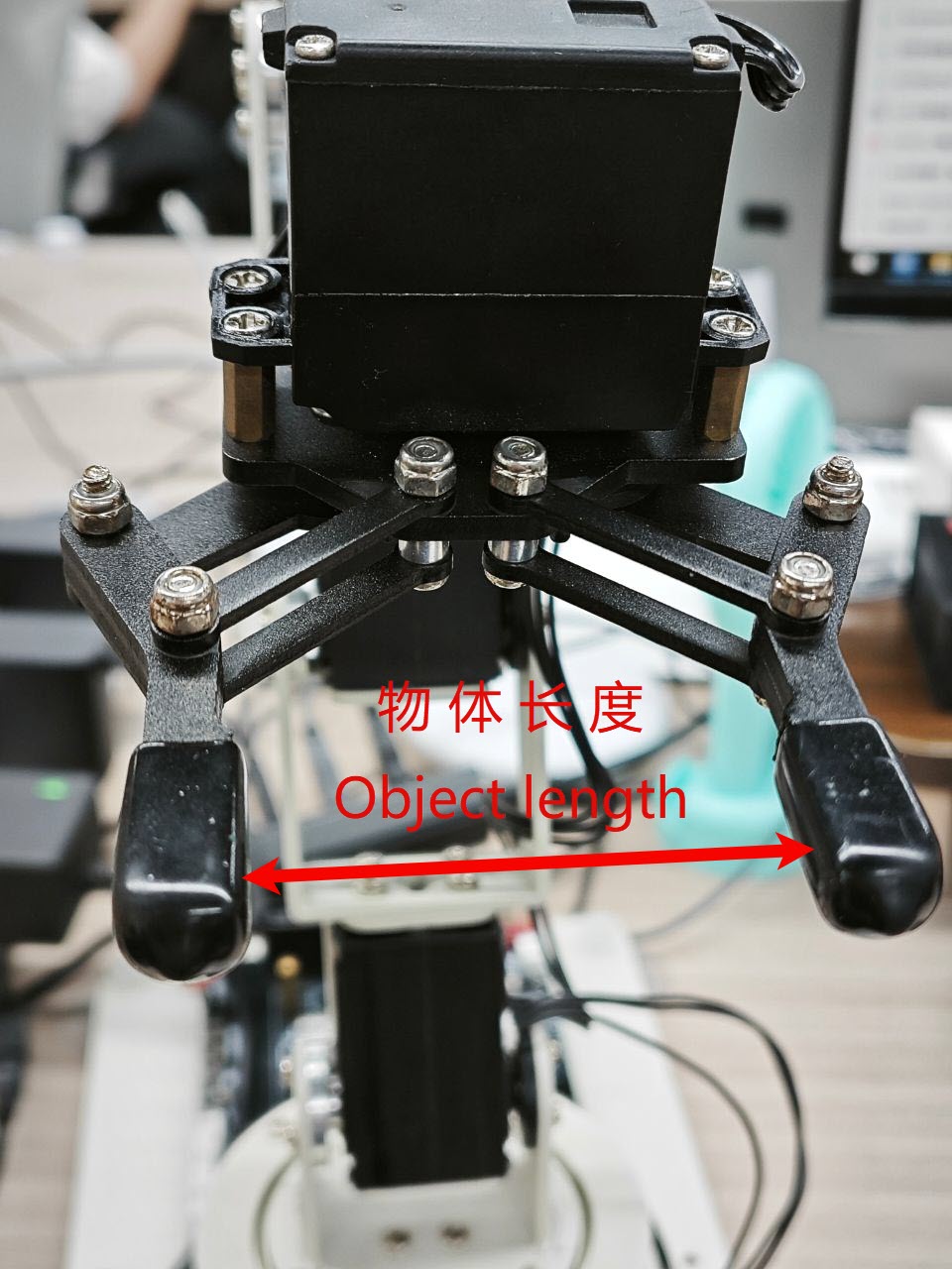
| Object length (unit: cm) | Servo angle (unit: degree) |
|---|---|
| 0 | 180 |
| 0.5 | 176 |
| 1.0 | 168 |
| 1.5 | 160 |
| 2.0 | 152 |
| 2.5 | 143 |
| 3.0 | 134 |
| 3.5 | 125 |
| 4.0 | 115 |
| 4.5 | 105 |
| 5.0 | 95 |
| 5.5 | 80 |
| 6.0 | 57 |
| 6.0-6.4 | 0-57 |
Start JupyterLab
Make DOFBOT and your computer on the same LAN (the lab WiFi is Duckietown, password: quackquack)
-
If your DOFBOT is connected to the same LAN as your
PC via WiFi, you can access its Jupyter Lab by
entering the DOFBOT's IP address followed by port
`888X` in your browser, where X is the group number.
For example, if you are using account group1, you can access Jupyter Lab through port 8881. For group2, it will be at 8882, etc.
The general access student account is accessible at port 8880, and the admin jetson account is accessible at port 8888.
Password will be the same as the Dofbot account.
- For example: http://192.168.1.67:8881/ This would correspond to group1 user so password: group1
-
Replace
192.168.1.67with your actual DOFBOT IP address. -
As shown below:
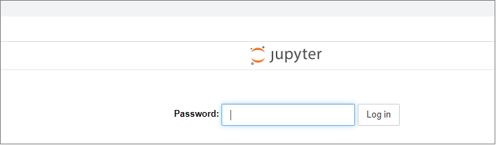
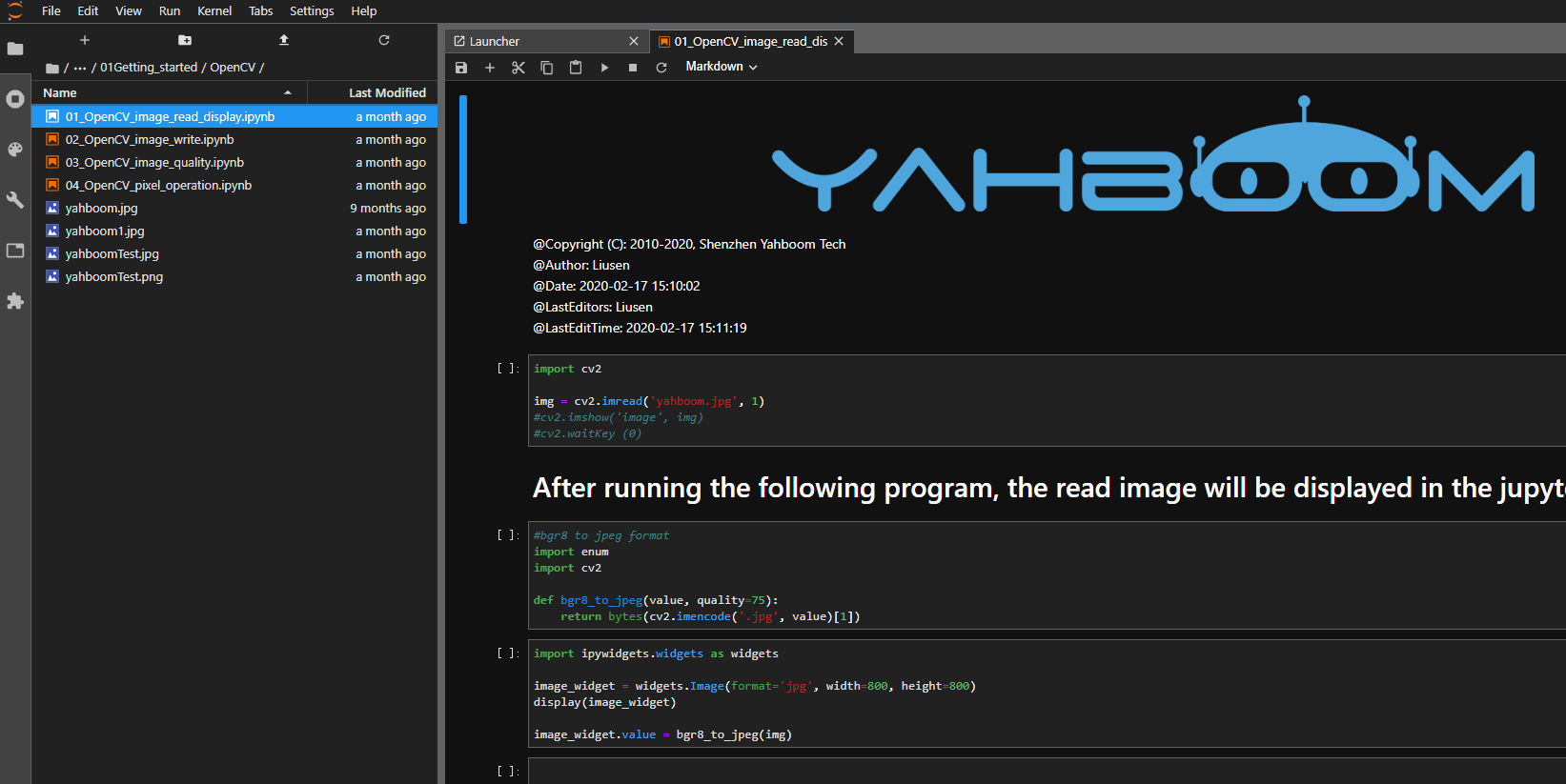
- You will see the Jupyter Lab interface:
- Navigate into the readonly_examples directory then enter Dofbot:
-
Inside, you will see several folders. Enter a folder
to access the code:
-
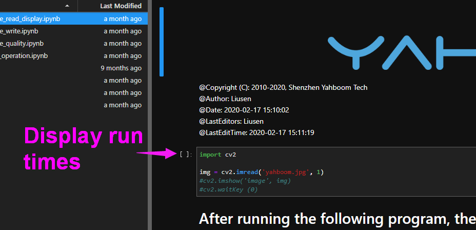
Click the Run button in the top
menu to execute the code:

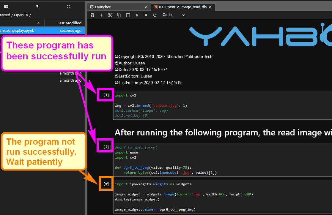
-
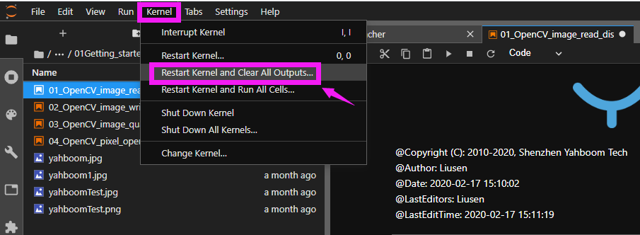
To exit and run another program, click the Kernel
menu and open a different file:
Control RGB light
The underlying firmware of the robot arm expansion board is developed separately. We provide an interface to allow users to call it. This underlying firmware is responsible for controlling the bus servos, PWM servos, and RGB lights.
The underlying driver source code has been packaged into a python library, and the underlying driver firmware has been installed in the system image provided by Yahboom.
If you want to transplant it to your own system, you can find the Dofbot.tar.gz compressed package in the program source code summary folder, and then remotely transfer it to the Raspberry Pi system through winscp software.
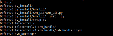
Enter the following command to decompress the firmware package.
After successful decompression, the following interface will appear.
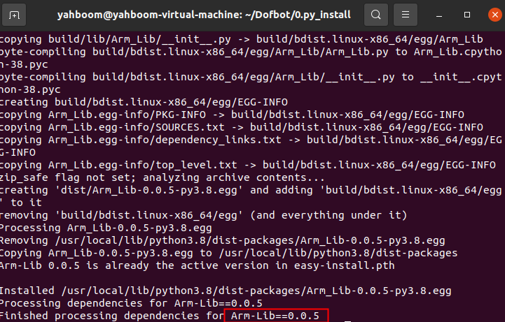
Then install it into the system through the following command:
Enter the user password and press Enter to confirm. If you see the installation prompt Arm_Lib=x.x.x version number, the installation is successful.
1.API Introduction
The corresponding API for RGB lights is:
Arm_RGB_set(R, G, B)
Sets the color of the RGB light on the robotic arm.
Parameters:
R- Brightness of the red light (0-255). Higher = brighter.
G- Brightness of the green light (0-255). Higher = brighter.
B- Brightness of the blue light (0-255). Higher = brighter.
Return Value:
None
2.Code content
Code path:
                            # Cycle through the RGB lights on the robot arm expansion board to illuminate red, green, and blue.
                            #!/usr/bin/env python3
                            #coding=utf-8
                            import time
                            from Arm_Lib import Arm_Device
                            # Get the object of the robotic arm
                            Arm = Arm_Device()
                            time.sleep(.1)
                            def main():
                                while True:
                                Arm.Arm_RGB_set(50, 0, 0) #RGB Red light on
                                time.sleep(.5)
                                Arm.Arm_RGB_set(0, 50, 0) #RGB Green light on
                                time.sleep(.5)
                                Arm.Arm_RGB_set(0, 0, 50) #RGB blue light on
                                time.sleep(.5)
                                print(" END OF LINE! ")
                            try :
                                main()
                            except KeyboardInterrupt:
                                # Release the Arm object
                                del Arm
                                print(" Program closed! ")
                                pass
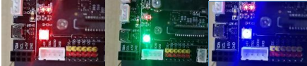
Open the 1.rgb.ipynb file from jupyter lab, and click the "Run" entire notebook button on the jupyter lab toolbar. You can see that the RGB light on the robot arm expansion board lights up red, green, and blue lights in a cycle every 0.5 seconds.
If you want to quit, click the Stop button on the toolbar.

Control buzzer
1. API Introduction
Arm_Buzzer_On(delay=255)
Turn on the buzzer.
Parameters:
delay- The input range of delay is 1~50. The larger the value, the longer the buzzer sounds. It will automatically turn off after timeout. The delay time is specified: 1=100 milliseconds, 2=200 milliseconds, and so on, up to the maximum The delay time is 50=5 seconds. If delay does not pass in a value or delay=255, it means that the buzzer beeps for a long time and needs to be turned off manually.
Return Value:
None
Arm_Buzzer_Off()
Turn off the buzzer.
Parameters:
- No parameters are passed in.
Return Value:
None
2. Code content
Code path:
                            #!/usr/bin/env python3
                            #coding=utf-8
                            import time
                            from Arm_Lib import Arm_Device

                            #Get the object of the robotic arm
                            Arm = Arm_Device()
                            time.sleep(.1)

                            # The buzzer automatically sounds for 100 milliseconds and then turns off.
                            b_time = 1
                            Arm.Arm_Buzzer_On(b_time)
                            time.sleep(1)

                            #The buzzer automatically sounds for 300 milliseconds and then turns off.
                            b_time = 3
                            Arm.Arm_Buzzer_On(b_time)
                            time.sleep(1)

                            # The buzzer keeps beeping
                            Arm.Arm_Buzzer_On()
                            time.sleep(1)

                            #Turn off the buzzer
                            Arm.Arm_Buzzer_Off()
                            time.sleep(1)

                            del Arm # Release Arm object p
Open the 2.beep.ipynb file from jupyter lab and click the Run entire notebook button on the jupyter lab toolbar.You can hear the buzzer on the expansion board beeping three times in a row, and the sound from the back is longer than the sound from the front.

It will automatically exit after the operation is completed.
Control single servo
1. API Introduction
The API corresponding to controlling a single bus servo is:
Arm_serial_servo_write(id, angle, time)
Control the angle to which the bus servo will run.
Parameters:
id- The ID number of the servo to be controlled, ranging from 1 to 6. Each ID number represents a servo. The ID of the bottom servo is 1 and increases upwards. The ID of the top servo is 6.
Angle- The angle to which the servo is to be controlled. Except for the No. 5 servo (ID=5), the control range of the other servos is 0~180, and the control range of the No. 5 servo is 0~270.
Time- Controls the time the servo runs. Within the valid range, the servo rotates at the same angle. The smaller the input running time, the faster the servo moves. Entering 0 will cause the servo to run at the fastest speed.
Return Value:
None
2. Code content
Code path:
                            #!/usr/bin/env python3
                            #coding=utf-8
                            import time
                            from Arm_Lib import Arm_Device
                            # Create a robotic arm object
                            Arm = Arm_Device()
                            time.sleep(.1)

                            # Individually control a servo to move to a certain angle
                            id = 6
                            Arm.Arm_serial_servo_write(id, 90, 500)
                            time.sleep(1)

                            # Control a servo to switch angles cyclically
                            id = 6
                            def main():
                                while True:
                                Arm.Arm_serial_servo_write(id, 120, 500)
                                time.sleep(1)
                                Arm.Arm_serial_servo_write(id, 50, 500)
                                time.sleep(1)
                                Arm.Arm_serial_servo_write(id, 120, 500)
                                time.sleep(1)
                                Arm.Arm_serial_servo_write(id, 180, 500)
                                time.sleep(1)

                            try :
                                main()
                            except KeyboardInterrupt:
                                print(" Program closed! ")
                                pass

                            del Arm # ReleaseArm object
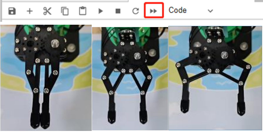
Open the program file from jupyter lab and click the run entire notebook button on the jupyter lab toolbar. You can see that the claws of the robotic arm are constantly changing angles.
If you want to quit, click the Stop button on the toolbar.

Read the current position of the servo
1. API Introduction
The API corresponding to reading the angle of a single bus servo is:
Arm_serial_servo_read(id)
Read the current angle value of the bus servo.
Parameters:
id- The ID number of the servo to be read, ranging from 1 to 6. Each ID number represents a servo. The ID of the bottom servo is 1 and increases upwards. The ID of the top servo is 6.
Return Value:
The current angle of the corresponding
                                        ID servo. When ID=5, the angle range is
                                        0~270, and otherwise it is 0~180.
2. Code content
Code path:
                            #!/usr/bin/env python3
                            #coding=utf-8
                            import time
                            from Arm_Lib import Arm_Device
                            # Create robot arm object
                            Arm = Arm_Device()
                            time.sleep(.1)

                            # Read the angles of all servos and print them out in a loop
                            def main():
                                while True:
                                    for i in range(6):
                                    aa = Arm.Arm_serial_servo_read(i+1)
                                    print(aa)
                                    time.sleep(.01)
                                    time.sleep(.5)
                                    print(" END OF LINE! ")
                            try :
                                main()
                            except KeyboardInterrupt:
                                print(" Program closed! ")
                                pass

                            # After controlling the movement of a servo separately, read its angle.
                            id = 6
                            angle = 150
                            Arm.Arm_serial_servo_write(id, angle, 500)
                            time.sleep(1)
                            aa = Arm.Arm_serial_servo_read(id)
                            print(aa)
                            time.sleep(.5)

                            del Arm # Release Arm object
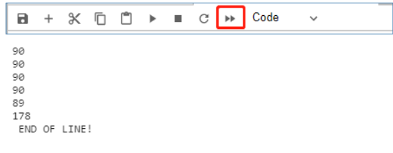
Open the program file from jupyter lab and click the Run entire notebook button on the jupyter lab toolbar. Jupyter lab will print out the angle values of the six servos of the current robotic arm.
If you want to quit, click the Stop button on the toolbar.

Control all servo
1. API Introduction
The API corresponding to controlling 6 bus servos at one time is:
Arm_serial_servo_write6(S1, S2, S3, S4,
                                        S5, S6, time)
Simultaneously control the angle to which the six servos of the robotic arm are to move.
Parameters:
S1- Angle value of No. 1 servo 0~180.
S2- Angle value of No. 2 servo 0~180.
S3- Angle value of No. 3 servo 0~180.
S4- Angle value of No. 4 servo is 0~180.
S1=5- Angle value of No. 5 servo is 0~270.
S6- Angle value of servo No. 6 is 0~180.
Time- Controls the time the servo runs. Within the valid range, the servo rotates at the same angle. The smaller the input running time, the faster the servo moves. Entering 0 will cause the servo to run at the fastest speed.
Return Value:
None
2. Code content
Code path:
                            #!/usr/bin/env python3
                            #coding=utf-8
                            import time
                            from Arm_Lib import Arm_Device
                            # Create robot arm object
                            Arm = Arm_Device()
                            time.sleep(.1)

                            # Control the movement of six servos at the same time and gradually change the angle.
                            def ctrl_all_servo(angle, s_time = 500):
                                Arm.Arm_serial_servo_write6(angle, 180-angle, angle, angle, angle, angle, s_time)
                                time.sleep(s_time/1000)

                            def main():
                                dir_state = 1
                                angle = 90

                                # Reset the servo to center
                                Arm.Arm_serial_servo_write6(90, 90, 90, 90, 90, 90, 500)
                                time.sleep(1)

                                while True:
                                    if dir_state == 1:
                                        angle += 1
                                    if angle >= 180:
                                        dir_state = 0
                                    else:
                                        angle -= 1
                                    if angle <= 0:
                                        dir_state = 1

                                    ctrl_all_servo(angle, 10)
                                    time.sleep(10/1000)
                                # print(angle)

                            try :
                                main()
                            except KeyboardInterrupt:
                                print(" Program closed! ")
                                pass

                            del Arm # Release Arm object
Open the program file from jupyter lab and click the Run entire notebook button on the jupyter lab toolbar. You can see that the six servos of the robotic arm rotate at the same time and the robotic arm continuously changes its posture.

If you want to quit, click the Stop button on the toolbar.
DOFBOT grab block
1. Game introduction
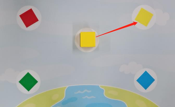
The purpose of this experiment is to move the blocks from the gray area in the middle to the surrounding square areas of different colors. First put the yellow block into the gray area, and then run the code unit to the sixth unit in sequence (grab a building block from the gray building block and place it on the yellow building block). At this time, the robot arm will automatically grab the block placed in the gray area, then place it in the yellow area, and then return to the ready position. Before running the seventh code unit, you need to place the red block in the gray area, and then run the seventh unit (grab a building block from the gray building block and place it on the red building block),In this way, red squares will also be captured to the red area, and other squares will be operated in the same way.
2. Code content
Code path:
The following code content needs to be executed according to the actual step, and cannot be run all at once. Before picking up the building blocks, you need to place the building blocks on the gray building blocks in the middle, and only one block can be placed at a time.
                            #!/usr/bin/env python3
                            #coding=utf-8
                            import time
                            from Arm_Lib import Arm_Device
                            # Create robot arm object
                            Arm = Arm_Device()
                            time.sleep(.1)

                            # Define the function of clamping building blocks, enable=1:clamp, =0:release
                            def arm_clamp_block(enable):
                                if enable == 0:
                                    Arm.Arm_serial_servo_write(6, 60, 400)
                                else:
                                    Arm.Arm_serial_servo_write(6, 130, 400)
                                    time.sleep(.5)

                            # Define the mobile robot arm function and control the movement of servos No. 1-5 at the same time, p=[S1,S2,S3,S4,S5]
                            def arm_move(p, s_time = 500):
                                for i in range(5):
                                    id = i + 1
                                    if id == 5:
                                        time.sleep(.1)
                                        Arm.Arm_serial_servo_write(id, p[i], int(s_time*1.2))
                                    else:
                                        Arm.Arm_serial_servo_write(id, p[i], s_time)
                                    time.sleep(.01)
                                time.sleep(s_time/1000)

                            # Robotic arm moves up
                            def arm_move_up():
                                Arm.Arm_serial_servo_write(2, 90, 1500)
                                Arm.Arm_serial_servo_write(3, 90, 1500)
                                Arm.Arm_serial_servo_write(4, 90, 1500)
                                time.sleep(.1)

                            # Define variable parameters at different locations
                            p_mould = [90, 130, 0, 0, 90]
                            p_top = [90, 80, 50, 50, 270]
                            p_Brown = [90, 53, 33, 36, 270]
                            p_Yellow = [65, 22, 64, 56, 270]
                            p_Red = [117, 19, 66, 56, 270]
                            p_Green = [136, 66, 20, 29, 270]
                            p_Blue = [44, 66, 20, 28, 270]

                            # Let the robotic arm move to a position ready to grab
                            arm_clamp_block(0)
                            arm_move(p_mould, 1000)
                            time.sleep(1)

                            # Grab a building block from the gray building block and place it on the yellow building block.
                            arm_move(p_top, 1000)
                            arm_move(p_Brown, 1000)
                            arm_clamp_block(1)
                            arm_move(p_top, 1000)
                            arm_move(p_Yellow, 1000)
                            arm_clamp_block(0)
                            arm_move(p_mould, 1000)
                            time.sleep(1)

                            # Grab a building block from the gray building block and place it on the red building block.
                            arm_move(p_top, 1000)
                            arm_move(p_Brown, 1000)
                            arm_clamp_block(1)
                            arm_move(p_top, 1000)
                            arm_move(p_Red, 1000)
                            arm_clamp_block(0)
                            arm_move_up()
                            arm_move(p_mould, 1100)
                            time.sleep(1)

                            # Grab a building block from the gray building block and place it on the green building block.
                            arm_move(p_top, 1000)
                            arm_move(p_Brown, 1000)
                            arm_clamp_block(1)
                            arm_move(p_top, 1000)
                            arm_move(p_Green, 1000)
                            arm_clamp_block(0)
                            arm_move_up()
                            arm_move(p_mould, 1100)
                            time.sleep(1)

                            # Grab a building block from the gray building block and place it on the blue building block.
                            arm_move(p_top, 1000)
                            arm_move(p_Brown, 1000)
                            arm_clamp_block(1)
                            arm_move(p_top, 1000)
                            arm_move(p_Blue, 1000)
                            arm_clamp_block(0)
                            arm_move_up()
                            arm_move(p_mould, 1100)
                            time.sleep(1)

                            del Arm # Release Arm object
Porter
1. Introduction to gameplay
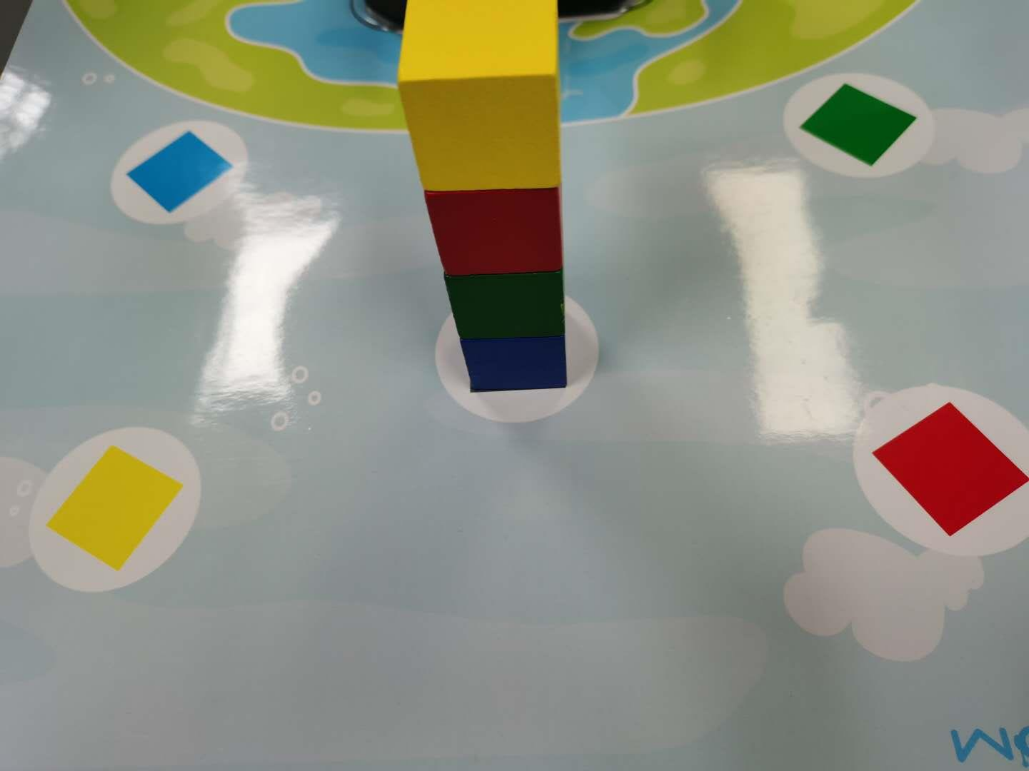
The purpose of this experiment is to stack four building blocks of different colors from bottom to top in the order of blue, green, red and yellow, place them on the middle gray square, and then run the code.
The robot arm will pick up the fourth layer of blocks and place them in the yellow area, pick up the third layer blocks and place them in the red area, pick up the second layer blocks and put them in the green area, and pick up the bottom blocks and place them in the blue area,Execute in order.The way to place the building blocks is as shown in the figure below:
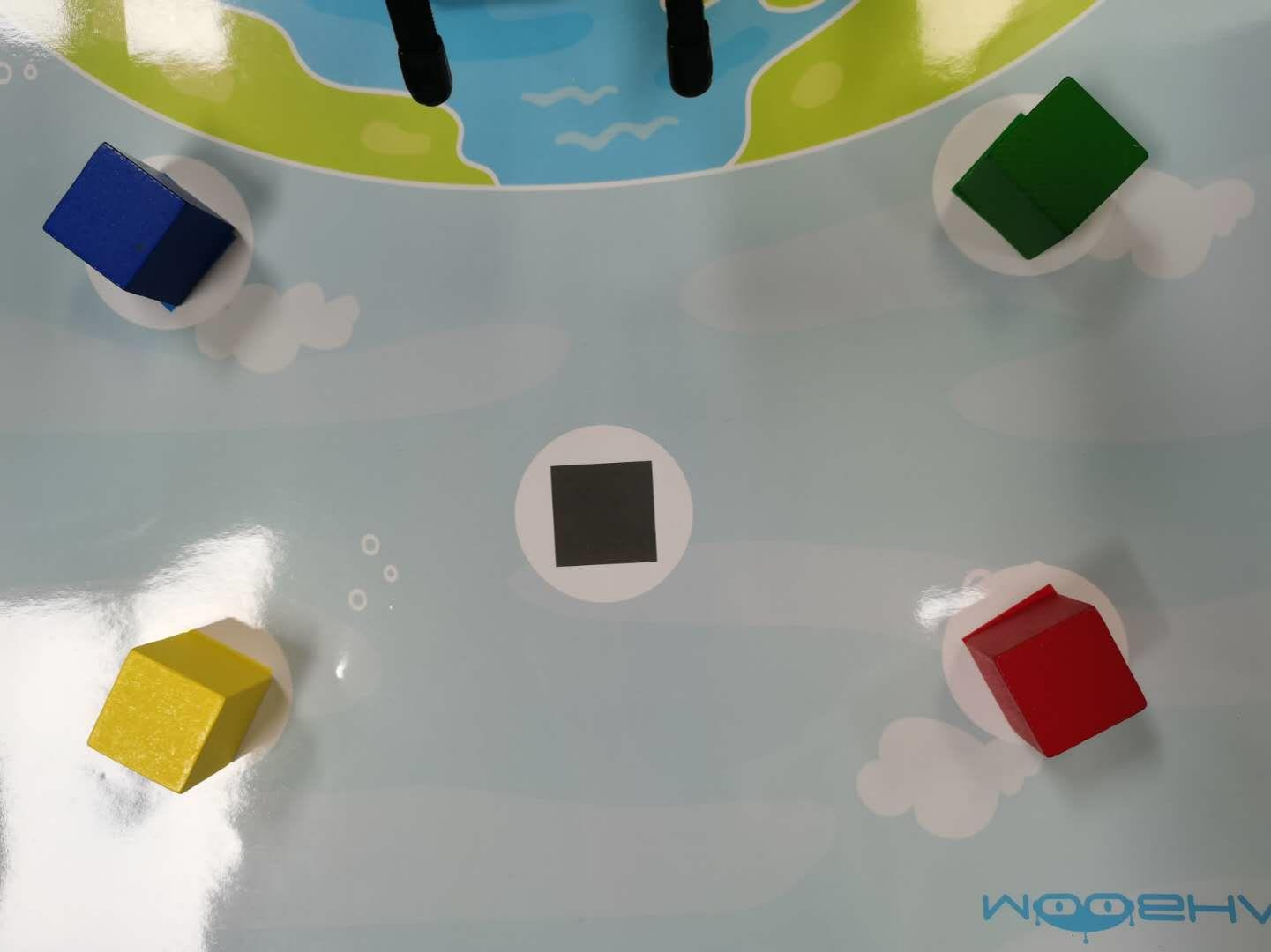
After executing the code, the robot arm will carry the building blocks to the corresponding position. The final effect is as shown in the figure below:
2. Code content
Code path:
                            #!/usr/bin/env python3
                            #coding=utf-8
                            import time
                            from Arm_Lib import Arm_Device
                            # Create robot arm object
                            Arm = Arm_Device()
                            time.sleep(.1)

                            # Define the function of clamping building blocks, enable=1:clamp, =0:release
                            def arm_clamp_block(enable):
                                if enable == 0:
                                    Arm.Arm_serial_servo_write(6, 60, 400)
                                else:
                                    Arm.Arm_serial_servo_write(6, 130, 400)
                                    time.sleep(.5)

                            # Define the mobile robot arm function and control the movement of servos No. 1-5 at the same time, p=[S1,S2,S3,S4,S5]
                            def arm_move(p, s_time = 500):
                                for i in range(5):
                                    id = i + 1
                                    if id == 5:
                                        time.sleep(.1)
                                        Arm.Arm_serial_servo_write(id, p[i], int(s_time*1.2))
                                    else :
                                        Arm.Arm_serial_servo_write(id, p[i], s_time)
                                    time.sleep(.01)
                                time.sleep(s_time/1000)

                            # Robotic arm moves up
                            def arm_move_up():
                                Arm.Arm_serial_servo_write(2, 90, 1500)
                                Arm.Arm_serial_servo_write(3, 90, 1500)
                                Arm.Arm_serial_servo_write(4, 90, 1500)
                                time.sleep(.1)

                            # Define variable parameters at different locations
                            p_mould = [90, 130, 0, 0, 90]
                            p_top = [90, 80, 50, 50, 270]
                            p_Yellow = [65, 22, 64, 56, 270]
                            p_Red = [117, 19, 66, 56, 270]
                            p_Green = [136, 66, 20, 29, 270]
                            p_Blue = [44, 66, 20, 28, 270]
                            p_layer_4 = [90, 72, 49, 13, 270]
                            p_layer_3 = [90, 66, 43, 20, 270]
                            p_layer_2 = [90, 63, 34, 30, 270]
                            p_layer_1 = [90, 53, 33, 36, 270]

                            # Let the robotic arm move to a position ready to grab
                            arm_clamp_block(0)
                            arm_move(p_mould, 1000)
                            time.sleep(1)
                            # Move the building blocks on the fourth floor to the yellow area
                            arm_move(p_top, 1000)
                            arm_move(p_layer_4, 1000)
                            arm_clamp_block(1)
                            arm_move(p_top, 1000)
                            arm_move(p_Yellow, 1000)
                            arm_clamp_block(0)
                            time.sleep(.1)
                            arm_move_up()
                            arm_move(p_mould, 1100)

                            # time.sleep(1)

                            # Move the third layer of building blocks to the red area
                            arm_move(p_top, 1000)
                            arm_move(p_layer_3, 1000)
                            arm_clamp_block(1)
                            arm_move(p_top, 1000)
                            arm_move(p_Red, 1000)
                            arm_clamp_block(0)
                            time.sleep(.1)
                            arm_move_up()
                            arm_move(p_mould, 1100)

                            # time.sleep(1)

                            # Carry the second layer of building blocks to the green area
                            arm_move(p_top, 1000)
                            arm_move(p_layer_2, 1000)
                            arm_clamp_block(1)
                            arm_move(p_top, 1000)
                            arm_move(p_Green, 1000)
                            arm_clamp_block(0)
                            time.sleep(.1)
                            arm_move_up()
                            arm_move(p_mould, 1100)

                            # time.sleep(1)

                            # Move the first layer of building blocks to the blue area
                            arm_move(p_top, 1000)
                            arm_move(p_layer_1, 1000)
                            arm_clamp_block(1)
                            arm_move(p_top, 1000)
                            arm_move(p_Blue, 1000)
                            arm_clamp_block(0)
                            time.sleep(.1)
                            arm_move_up()
                            arm_move(p_mould, 1100)

                            # time.sleep(1)

                            del Arm #Release Arm object
Stacked Arhat
1. Introduction to gameplay
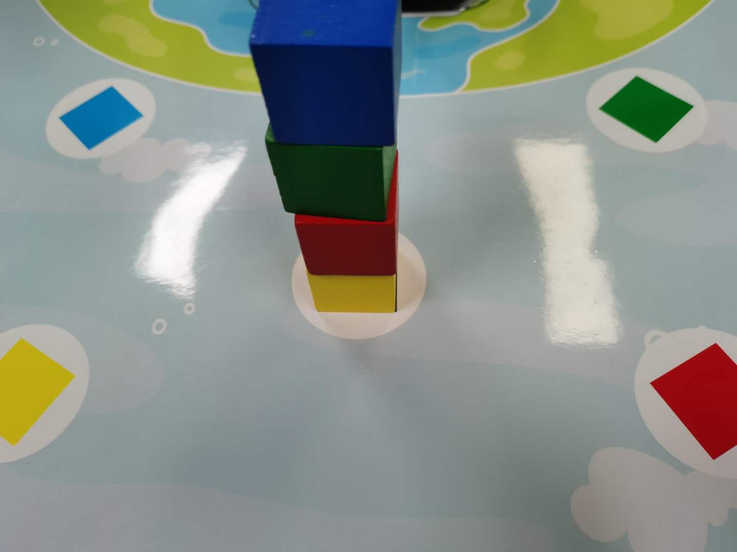
The purpose of this experiment is exactly the opposite of the previous lesson "Nature Porter". It is to pick up the building blocks from different sides in the order of yellow, red, green and blue and stack them into the gray area in the middle.
The way to place the building blocks is as shown in the figure below:
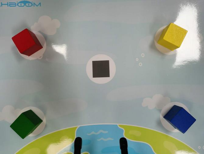
After executing the code, the robotic arm will stack the building blocks, and the final effect is as shown in the figure below:
2. Code content
Code path:
                            #!/usr/bin/env python3
                            #coding=utf-8
                            import time
                            from Arm_Lib import Arm_Device
                            # Create robot arm object
                            Arm = Arm_Device()
                            time.sleep(.1)

                            # Define the function of clamping building blocks,enable=1:clamp,=0:release
                            def arm_clamp_block(enable):
                                if enable == 0:
                                    Arm.Arm_serial_servo_write(6, 60, 400)
                                else:
                                    Arm.Arm_serial_servo_write(6, 130, 400)
                                    time.sleep(.5)

                            # Define the mobile robot arm function and control the movement of servos No. 1-5 at the same time,p=[S1,S2,S3,S4,S5]
                            def arm_move(p, s_time = 500):
                                for i in range(5):
                                    id = i + 1
                                    if id == 5:
                                        time.sleep(.1)
                                        Arm.Arm_serial_servo_write(id, p[i], int(s_time*1.2))
                                    elif id == 1 :
                                        Arm.Arm_serial_servo_write(id, p[i], int(3*s_time/4))
                                    else:
                                        Arm.Arm_serial_servo_write(id, p[i], int(s_time))
                                    time.sleep(.01)
                                time.sleep(s_time/1000)

                            # Define variable parameters at different locations
                            p_mould = [90, 130, 0, 0, 90]
                            p_top = [90, 80, 50, 50, 270]
                            p_layer_4 = [90, 76, 40, 17, 270]
                            p_layer_3 = [90, 65, 44, 17, 270]
                            p_layer_2 = [90, 65, 25, 36, 270]
                            p_layer_1 = [90, 48, 35, 30, 270]
                            p_Yellow = [65, 22, 64, 56, 270]
                            p_Red = [118, 19, 66, 56, 270]
                            p_Green = [136, 66, 20, 29, 270]
                            p_Blue = [44, 66, 20, 28, 270]

                            # Let the robotic arm move to a position ready to grab
                            arm_clamp_block(0)
                            arm_move(p_mould, 1000)
                            time.sleep(1)

                            # Stack the blocks in the yellow area to the bottom position in the middle.
                            arm_move(p_top, 1000)
                            arm_move(p_Yellow, 1000)
                            arm_clamp_block(1)
                            arm_move(p_top, 1000)
                            arm_move(p_layer_1, 1000)
                            arm_clamp_block(0)
                            time.sleep(.1)
                            arm_move(p_mould, 1100)

                            # time.sleep(1)

                            # Stack the blocks in the red area to the second layer in the middle.
                            arm_move(p_top, 1000)
                            arm_move(p_Red, 1000)
                            arm_clamp_block(1)
                            arm_move(p_top, 1000)
                            arm_move(p_layer_2, 1000)
                            arm_clamp_block(0)
                            time.sleep(.1)
                            arm_move(p_mould, 1100)
                            # time.sleep(1)

                            # Stack the blocks in the green area to the third layer in the middle.
                            arm_move(p_top, 1000)
                            arm_move(p_Green, 1000)
                            arm_clamp_block(1)
                            arm_move(p_top, 1000)
                            arm_move(p_layer_3, 1000)
                            arm_clamp_block(0)
                            time.sleep(.1)
                            arm_move(p_mould, 1100)

                            # time.sleep(1)

                            # Stack the blocks in the blue area to the fourth layer in the middle.
                            arm_move(p_top, 1000)
                            arm_move(p_Blue, 1000)
                            arm_clamp_block(1)
                            arm_move(p_top, 1000)
                            arm_move(p_layer_4, 1000)
                            arm_clamp_block(0)
                            time.sleep(.1)
                            arm_move(p_mould, 1100)

                            # time.sleep(1)

                            del Arm # Release Arm object
USB camera display
1. Camera reading
capture=cv.VideoCapture(0)
Turn on the buzzer.
Parameters:
- The parameter in VideoCapture() is 0, which means opening the laptop's built-in camera. If the parameter is the video file path, the video will be opened, such as cap = cv2.VideoCapture("../test.avi")
2. Display camera video
ret,img = frame.read()
Turn off the buzzer.
Return Value:
ret- ret is a bool value to determine whether the correct frame is read back.
img- image data of each frame
3. Code and actual effect display
Program path:
Main code:
                            import cv2
                            import ipywidgets.widgets as widgets
                            import threading
                            import time

                            image_widget = widgets.Image(format='jpeg', width=600, height=500)  #Set up the camera display component
                            display(image_widget)                                               #Show camera components

                            #bgr8 to jpeg format
                            import enum
                            import cv2

                            def bgr8_to_jpeg(value, quality=75):
                                return bytes(cv2.imencode('.jpg', value)[1])

                            image = cv2.VideoCapture(0,cv2.CAP_V4L2)                   #open camera
                            ret, frame = image.read()
                            image_widget.value = bgr8_to_jpeg(frame)
After the code block is run, the picture captured by the USB camera can be displayed.
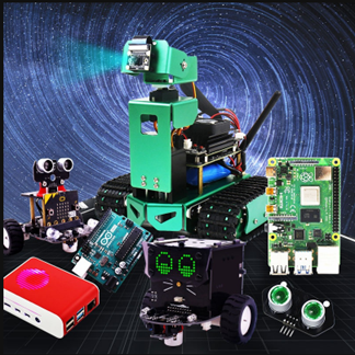
Introduction to Open Source CV

What is OpenCV? Its full name is Open source Computer Vision Library, open source computer vision library.As shown in the picture above, what we see is the OpenCV logo. We can see that it consists of three small rings in the three distinct primary colors of R, G, and B.In other words, it is a set of open source API function libraries about computer vision. This also means,
- Whether it is scientific reserach or commerical application, it can be used for development;
- The source code of all API functions is public, and you can see the program steps of its internal implementation;
- You can modify the source code of OpenCV and compile and generate the specific API functions you need.
Image processing on ROSMASTER uses certain functions of the OpenCV function library, or it can be said that it is inseparable from its existence in most image processing design fields.As early as many years ago, OpenCV has been showing its talents in the fields of intrusion detection, specific target tracking, target detection, face detection, face recognition, face tracking, etc., and these are just the tip of the iceberg of its applications. Since we realize that OpenCV is so versatile, in this chapter we will introduce you to some very basic image processing functions that we use in our courses, as well as some universal functions.Here we first have a general understanding of this knowledge, and then there are two practical projects on color recognition and tracking, and face recognition and tracking to teach you how to get started. However, the powerful application functions provided by OpenCV are far more than this.If you are interested in Opencv computer vision library development and want to learn more about it, here are several websites for your reference and study:
OpenCV Official homepage: https://www.opencv.org/
OpenCV Chinese forum: http://www.opencv.org.cn/
OpenCV CSDN forum: https://bbs.csdn.net/forums/OpenCV
Image reading and display
1. Reading of images:
img = cv2.imread('yahboom.jpg', 0)
Parameters:
'yahboom.jpg'- The first parameter is the path of the image.
0- second parameter is how to read the image.
cv2.IMREAD_UNCHANGED
Keep the original format unchanged, -1;
cv2.IMREAD_GRAYSCALE
Read the image in grayscale mode, which can be represented by 0;
cv2.IMREAD_COLOR
Read a color picture, which can be represented by 1; default value
cv2.IMREAD_UNCHANGED:
Read in an image and include its alpha channel, which can be represented by 2.
2. Image display
cv.imshow('frame', frame)
Open a window named frame and display frame data (image/video data)
Parameters:
'frame'- The first parameter represents the name of the window that is created and opened.
frame- The second parameter represents the image to be displayed
2.1 Code and actual effect display
Code path:
Main code:
                            import cv2
                            img = cv2.imread('yahboom.jpg', 1)
                            # cv2.imshow('image', img)  #This line can only be executed from the py file on the command line, and a video window will pop up.
                            # cv2.waitKey (0)

                            #bgr8 to jpeg format
                            import enum
                            import cv2
                            def bgr8_to_jpeg(value, quality=75):
                            return bytes(cv2.imencode('.jpg', value)[1])

                            # The image component in jupyterLab displays the read image
                            import ipywidgets.widgets as widgets
                            image_widget = widgets.Image(format='jpg', width=800, height=800)
                            display(image_widget)
                            image_widget.value = bgr8_to_jpeg(img)
After running the code block, you can see the following interface, and the image has been read out.
Open Source CV image processing and drawing text line segments
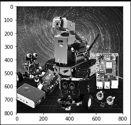
1.Grayscale processing
The process of converting a color image into a grayscale image is the grayscale processing of the image. The color of each pixel in a color image is determined by three components: R, G, and B.Each component can take a value of 0-255, so that one pixel can have a color range of more than 16 million (256256256=1677256).A grayscale image is a special color image with the same three components of R, G, and B. The range of changes of one pixel is 256.Therefore, in digital image processing, images in various formats are generally converted into grayscale images to make subsequent images less computationally intensive. The description of a grayscale image, like a color image, still reflects the distribution and characteristics of the overall and local chroma and highlight levels of the entire image.
Image grayscale processing: Grayscale processing is the process of converting a color image into a grayscale image. The color image is divided into three components: R, G, and B, which display various colors such as red, green, and blue respectively. Grayscale is the process of making the color R, G, and B components equal. Pixels with large grayscale values are brighter (the maximum pixel value is 255, which is white), and vice versa (the lowest pixel is 0, which is black).
The core idea of image grayscale is R = G = B. This value is also called grayscale value.
Image grayscale algorithm
- Maximum value method: Make the converted values of R, G, and B equal to the largest of the three values before conversion, that is: R=G=B=max (R, G, B). The grayscale image converted by this method is very bright.
- Average method: The values of R, G, and B after conversion are the average values of R, G, and B before conversion. That is: R=G=B=(R+G+B)/3. This method produces softer grayscale images.
- Weighted average method: According to a certain weight, the values of R, G, and B are weighted and averaged, that is, the weights of R, G, and B are respectively, and different values are taken to form different grayscale images. . Since the human eye is most sensitive to green, followed by red, and least sensitive to blue, a grayscale image that is easier to identify will be obtained. **Generally, the grayscale image obtained is the best.
There are four methods to achieve grayscale in the following code:
Code path:
                            #Method 1 imread
                            #Note: Sometimes the picture will not be displayed the first time you run it, but will be displayed the second time.
                            import cv2
                            import matplotlib.pyplot as plt
                            img0 = cv2.imread('yahboom.jpg',0)
                            img1 = cv2.imread('yahboom.jpg',1)
                            #   print(img0.shape)
                            #   print(img1.shape)
                            #   cv2.imshow('src',img0)
                            #   cv2.waitKey(0)

                            #original image
                            #   img_bgr2rgb1 = cv2.cvtColor(img1, cv2.COLOR_BGR2RGB)
                            #   plt.imshow(img_bgr2rgb1)

                            #gray image
                            img_bgr2rgb0 = cv2.cvtColor(img0, cv2.COLOR_BGR2RGB)
                            plt.imshow(img_bgr2rgb0)
                            plt.show()

                            #Method 2 cvtColor
                            #Note: Sometimes the picture will not be displayed the first time you run it, but will be displayed the second time.

                            import cv2
                            import matplotlib.pyplot as plt

                            img = cv2.imread('image0.jpg',1)
                            dst = cv2.cvtColor(img,cv2.COLOR_BGR2GRAY)#   color space conversion 1 data 2 BGR gray
                            #cv2.imshow('dst',dst)
                            #cv2.waitKey(0)

                            #original image
                            # img_bgr2rgb1   = cv2.cvtColor(img, cv2.COLOR_BGR2RGB)
                            # plt.imshow(img_bgr2rgb1)

                            #gray image
                            img_bgr2rgb0   = cv2.cvtColor(dst, cv2.COLOR_BGR2RGB)
                            plt.imshow(img_bgr2rgb0)
                            plt.show()

                            #Method 3 Average method

                            import cv2
                            import numpy as np
                            import matplotlib.pyplot as plt
                            img = cv2.imread('yahboom.jpg',1)
                            imgInfo = img.shape
                            height = imgInfo[0]
                            width = imgInfo[1]
                            # RGB R=G=B   = gray  (R+G+B)/3
                            dst = np.zeros((height,width,3),np.uint8)
                            for i in range(0,height):
                                for j in range(0,width):
                                    (b,g,r) = img[i,j]
                                    gray = (int(b)+int(g)+int(r))/3
                                    dst[i,j] = np.uint8(gray)
                            #cv2.imshow('dst',dst)
                            #cv2.waitKey(0)
                            #original image
                            #   img_bgr2rgb1 = cv2.cvtColor(img, cv2.COLOR_BGR2RGB)
                            #   plt.imshow(img_bgr2rgb1)

                            #gray image
                            img_bgr2rgb0 = cv2.cvtColor(dst, cv2.COLOR_BGR2RGB)
                            plt.imshow(img_bgr2rgb0)
                            plt.show()
                            #Method 4 Weighted average method
                            # gray = r*0.299+g*0.587+b*0.114
                            import cv2
                            import numpy as np
                            img = cv2.imread('yahboom.jpg',1)
                            imgInfo = img.shape
                            height = imgInfo[0]
                            width = imgInfo[1]
                            dst = np.zeros((height,width,3),np.uint8)
                            for i in range(0,height):
                                for j in range(0,width):
                                    (b,g,r) = img[i,j]
                                    b = int(b)
                                    g = int(g)
                                    r = int(r)
                                    gray = r*0.299+g*0.587+b*0.114
                                    dst[i,j] = np.uint8(gray)
                            #cv2.imshow('dst',dst)
                            #cv2.waitKey(0)

                            #original image
                            #   img_bgr2rgb1 = cv2.cvtColor(img, cv2.COLOR_BGR2RGB)
                            #   plt.imshow(img_bgr2rgb1)

                            #gray image
                            img_bgr2rgb0 = cv2.cvtColor(dst, cv2.COLOR_BGR2RGB)
                            plt.imshow(img_bgr2rgb0)
                            plt.show()

Binary image
The core idea of binarization is to set a threshold, and the value greater than the threshold is 0 (black) or 255 (white), making the image called a black and white image. The threshold can be fixed or adaptive. The adaptive threshold is generally a comparison of a point pixel with the mean value of regional pixels or the weighted sum of Gaussian distribution at this point, in which a difference value may or may not be set.
Global threshold:
Threshold is provided in Python-OpenCV(threshold)Function:cv2.threshold(src, threshold, maxValue, method)
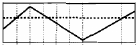
src original image: the dashed line is the value that will be thresholded; the dotted line is the threshold value
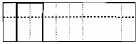
cv2.THRESH_BINARY: The gray value of pixels greater than the threshold is set to maxValue (for example, the maximum 8-bit gray value is 255), and the gray value of pixels whose gray value is less than the threshold is set to 0.
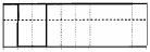
cv2.THRESH_BINARY_INV: The gray value of pixels greater than the threshold is set to 0, while the gray value of pixels less than the threshold is set to maxValue.
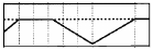
cv2.THRESH_TRUNC: The gray value of the pixel is less than the threshold and does not change. The pixel with a gray value greater than the threshold is set to the threshold.
cv2.THRESH_TOZERO: Pixels whose grayscale values are smaller than the threshold do not undergo any change, while pixels whose grayscale values are larger than the threshold are all changed to 0.
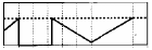
cv2.THRESH_TOZERO_INV: If the gray value of the pixel is greater than the threshold, no change will be made. If the gray value of the pixel is less than the threshold, all the gray values will be changed to 0.
Code path:
import cv2
import numpy as np
import matplotlib.pyplot as plt
img = cv2.imread('yahboom.jpg',1)
GrayImage = cv2.cvtColor(img, cv2.COLOR_BGR2GRAY) #Convert to grayscale image
ret,thresh1=cv2.threshold(GrayImage,10,255,cv2.THRESH_BINARY)
ret,thresh2=cv2.threshold(GrayImage,10,255,cv2.THRESH_BINARY_INV)
ret,thresh3=cv2.threshold(GrayImage,10,255,cv2.THRESH_TRUNC)
ret,thresh4=cv2.threshold(GrayImage,10,255,cv2.THRESH_TOZERO)
ret,thresh5=cv2.threshold(GrayImage,10,255,cv2.THRESH_TOZERO_INV)
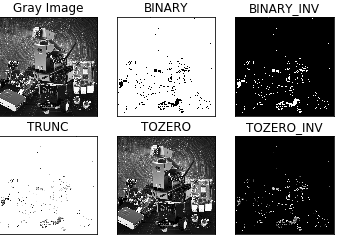
titles = ['Gray Image','BINARY','BINARY_INV','TRUNC','TOZERO','TOZERO_INV']
images = [GrayImage, thresh1, thresh2, thresh3, thresh4, thresh5]
for i in range(6):
plt.subplot(2,3,i+1),plt.imshow(images[i],'gray')
plt.title(titles[i])
plt.xticks([]),plt.yticks([])
plt.show()
Edge green detection
The purpose of edge detection is to significantly reduce the data size of the image while retaining the original image attributes. There are currently many algorithms for edge detection. Although the Canny algorithm is old, it can be said that it is a standard algorithm for edge detection and is still widely used in research. Canny edge detection is a technology that extracts useful structural information from different visual objects and greatly reduces the amount of data to be processed. It has been widely used in various computer vision systems. Canny found that the requirements for edge detection on different vision systems are relatively similar. Therefore, an edge detection technology with broad application significance can be implemented. General standards for edge detection include:
Detecting edges with a low error rate means capturing as many edges as possible in the image as accurately as possible. The detected edge should be located exactly at the center of the real edge. A given edge in the image should be marked only once, and where possible, noise in the image should not produce false edges. To meet these requirements, Canny uses the calculus of variations. The optimal function in the Canny detector is described by the sum of four exponential terms, which can be approximated by the first derivative of the Gaussian function.
Among the currently commonly used edge detection methods, the Canny edge detection algorithm is one of the strictly defined methods that can provide good and reliable detection. Because it has the advantages of meeting the three criteria of edge detection and being simple to implement, it has become one of the most popular algorithms for edge detection.
The Canny edge detection algorithm can be divided into the following 5 steps:
- Use Gaussian filter to smooth the image and filter out noise.
- Calculate the gradient intensity and direction of each pixel in the image.
- Apply non-maximum suppression to eliminate spurious responses caused by edge detection.
- Apply Double-Threshold detection to determine real and potential edges.
- Finally complete edge detection by suppressing isolated weak edges.
Code path:
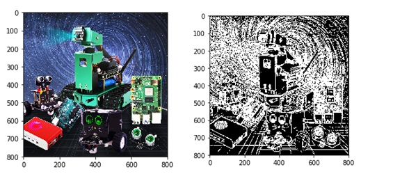
                                #Method 1
                                import cv2
                                import numpy as np
                                import random
                                import matplotlib.pyplot as plt

                                img = cv2.imread('image0.jpg',1)
                                imgInfo = img.shape
                                height = imgInfo[0]
                                width = imgInfo[1]
                                #cv2.imshow('src',img)
                                #canny 1   gray 2 gauss 3 canny
                                gray = cv2.cvtColor(img,cv2.COLOR_BGR2GRAY)
                                imgG = cv2.GaussianBlur(gray,(3,3),0)
                                dst = cv2.Canny(img,50,50) #Image convolution——》th
                                # cv2.imshow('dst',dst)
                                # cv2.waitKey(0)
Comparing two pictures
                                img_bgr2rgb1 = cv2.cvtColor(img, cv2.COLOR_BGR2RGB)
                                plt.imshow(img_bgr2rgb1)
                                plt.show()
                            img_bgr2rgb1 = cv2.cvtColor(dst, cv2.COLOR_BGR2RGB)
                            plt.imshow(img_bgr2rgb1)
                            plt.show()
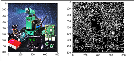
Code path:
                                #Method 2
                                import cv2
                                import numpy as np
                                import random
                                import math
                                img = cv2.imread('image0.jpg',1)
                                imgInfo = img.shape
                                height = imgInfo[0]
                                width = imgInfo[1]
                                # cv2.imshow('src',img)
                                # sobel 1 Operator template 2 Image convolution 3 Threshold judgment
                                # [1 2   1          [ 1 0 -1

                                #  0 0 0            2 0 -2
                                # -1 -2 -1   ]       1 0 -1 ]

                                # [1 2 3 4]   [a b c d] a*1+b*2+c*3+d*4 = dst
                                #   sqrt(a*a+b*b) = f>th

                                gray = cv2.cvtColor(img,cv2.COLOR_BGR2GRAY)
                                dst =  np.zeros((height,width,1),np.uint8)
                                for i in range(0,height-2):
                                    for j in range(0,width-2):
                                        gy = gray[i,j]*1+gray[i,j+1]*2+gray[i,j+2]*1-gray[i+2,j]*1-gray[i+2,j+1]*2-gray[i+2,j+2]*1

                                        gx = gray[i,j]+gray[i+1,j]*2+gray[i+2,j]-gray[i,j+2]-gray[i+1,j+2]*2-gray[i+2,j+2]

                                        grad = math.sqrt(gx*gx+gy*gy)
                                        if grad>50:
                                            dst[i,j] = 255
                                        else:
                                            dst[i,j] = 0
                                #   cv2.imshow('dst',dst)
                                    # cv2.waitKey(0)
App Control for Dofbot
Turn on app control:
python3 ~/Desktop/Arm/YahboomArm.pyc
Turn off app control (in a new terminal):
bash ~/Desktop/readonly_examples/Dofbot/kill_YahboomArm.sh
APP control
Remote Control
Click the *[Remote Control]* icon, the following interface will appear on APP.
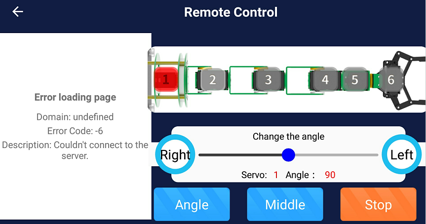
The camera screen is displayed on the left side of the APP. The numbers 1 to 6 on the schematic diagram of the DOFBOT represent the six servos. When we select the servo with the current ID number, the corresponding number will become red. Then, we can adjust the angle of the servo by dragging the slider or pressing left and right buttons.
[Angle]: After clicking this button, the APP will read the current servo angle, and update angle value to the upper slider.
[Middle]: DOFBOT returns to initial state.
[Stop]: Click this button, torque of the DOFBOT will be closed and stop receive control commands. We can manually control the angle of the servo.
Click this button again, torque of the DOFBOT will be opened, it will returns to initial state. And it starts receive control commands.