This project recreates the iconic Google Chrome Dinosaur Game (the offline “T-Rex Runner”)
using analog circuits, semiconductor devices, logic gates, and LEDS. Instead of a computer
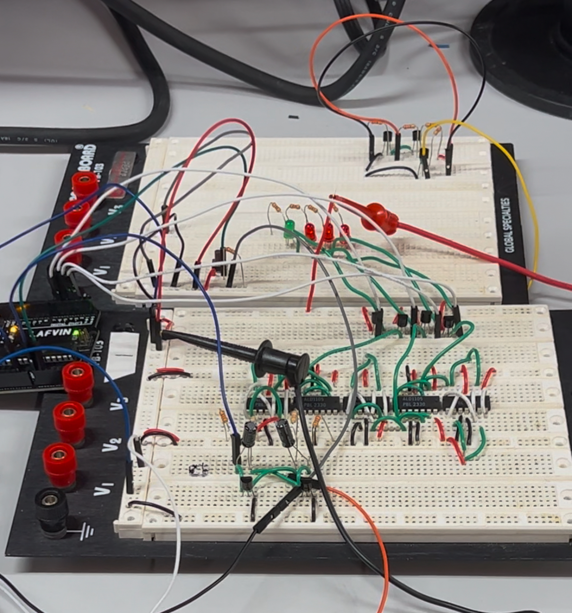
screen, the gameplay happens on a 4-LED array:
The leftmost LED represents the dinosaur.
The three right LEDs represent incoming obstacles.
Obstacles move left across the LEDs, one step per clock cycle.
The player must press a button at the correct time to jump and avoid collision.
If you mistime your jump, the dinosaur LED turns off—game over. The game increases in
challenge as the clock drives faster sequences.
Full bill of materials and references are documented in the project manual (see
References).
Technical Breakdown
Milestone 1 – Jumping & Timing
Astable multivibrator generates the clock (square wave).
Diode-based AND gate allows jump only while clock is HIGH.
Clock LED indicates valid jump window; Jump LED confirms action.
Milestone 2 – Memory & State
CMOS NAND + feedback to form D-latch behavior (Q follows D when enabled).
2N7000 MOSFET isolates LED load to preserve logic levels.
Sequential LED states represent obstacle positions.
Milestone 3 – Integrated Gameplay
Integrated timing + logic + memory into one loop.
Arduino used to compactly hold prior states (instead of ~6 discrete flip-flops).
Collision check via RTL AND (LED3 & no jump → lose condition).
Challenges & Trade-offs
Voltage drops from diode logic limited stage depth; moved toward CMOS.
Floating inputs / noise with buttons; slide switch for reliable edges.
Power constraints with RTL chains → current draw & level-shifting pain.
Scalability: Arduino substituted for a large bank of flip-flops.
Future Improvements
Debounced push button input (intuitive play + clean edges).
Player feedback (e.g., bi-color LED on fail; trailing LEDs for pass-by).
Dynamic difficulty via higher clock or multi-tick state steps.
Operate at lower voltage (e.g., 3.3V) to reduce power and heat.
Possible using PCB to make our circuit more compact.
What I Learned
Translating a digital game concept into analog timing and logic.
Practical limitations of diode, CMOS, and RTL logic gates in real-world circuits.
Balancing design complexity with project feasibility under time and power constraints.
How to use an Arduino as a hybrid analog/digital memory system.
Representative Code Snippet (Arduino)
//global variables
//ensures clock is only read once per up/down cycle
int CLOCK_HI = 0;
//lockout for jump
int jumped = 0;
//jump variable
int jump = 0;
//which LED was on in the previous state?
int LED0 = 0;
int LED1 = 0;
int LED2 = 0;
//trigger LED sequence
int LED = 0;
//game state
int game = 1;
//test
int enable = 0;
//score tracking
int score = 0;


void setup() {
  // put your setup code here, to run once:

  //pin declaration
  //LIGHT0
  pinMode(2, OUTPUT);
  //LIGHT1
  pinMode(3, OUTPUT);
  //LIGHT2
  pinMode(4, OUTPUT);
  //JUMP
  pinMode(5, OUTPUT);

  Serial.begin(9600);
}
For full code, see the Appendix in the manual.
References
Full design notes, schematics, operating conditions, and citations are documented in the project
manual (PDF).